Mechanical Infrastructure
Medical College of Georgia
Cooper Carry
Nottingham, Brook & Pennington
R. J. Griffin & Co.
13,305 Sq. Ft.
On the opposite end, two 1250-ton centrifugal chillers produce 7,000 GPM chilled water. Condenser water comes from the field-erected 4-cell cooling tower sitting atop a concrete basin designed and built to collect rainwater runoff from the Energy Plant.
The South Energy Plant at the Medical College of Georgia was constructed to support current and future growth. The process of heating high-pressure steam is produced by three 13,390 MBH fire tube Hurst boilers. The dual fuel boilers can operate on either natural gas or fuel oil. Steam condensate return is collected by two 1200-gallon condensate surge units and pumped to the deaerator for oxygen removal before feeding the boilers. Each boiler is fitted with a feed-water economizer to collect heat from the exhaust stack.
Steam and chilled water are distributed through an underground infrastructure of pre-insulated piping. The South Energy Plant will grow with the MCG campus with space to add a fourth boiler and five additional chillers.
Emory University
N/A
RMF Engineering
Negotiated
28,000
The intent of the project was to increase the capacity of the chilled water system at the Emory University Campus.
The mechanical upgrade pertained to the Quadrangle and Michael Street energy plants.
The Quadrangle energy plant system was provided with the following equipment:
Michael Street energy plant system was provided with the following equipment:
Micheal Street plant was also provided with a new 1500 KW emergency power generator. A new fuel tank with a 500-gallon capacity was installed.
Additional 16 inches of chilled water piping to connect the plant to the campus loop was provided. The emergency generator was equipped with a closed cooling loop using condenser water from the cooling towers farm.
University of Georgia
FPW Architects
RMF Engineering
Lump Sum Bid
The new Northwest Central Utility Plant (NW CUP) was built to accommodate 10,000 tons of cooling and heating hot water from campus distributed central steam system. Initial cooling capacity of the plant consisted of two (2) 1,000-ton electric centrifugal chiller systems complete with new condenser water pump; new roof mounted cooling towers, new chemical feed and filtration systems.
Emory University
RMF Engineering
Mann Mechanical Company, Inc.
Negotiated
Two Part
Part 1
Furnish and install 900 feet of pre-insulated steam and condensate pre-insulated piping. The overall project was handled as a Mechanical Prime and turned over as a turnkey contract.
This included all components consisting of:
The shut down and tie-ins of the new steam and condensate systems was performed after hours to limit disruptions to the end user.
Part 2
Demolish existing condensate storage tank and pumps and replace with new 1600gal steel storage tank with two end suction pumps designed for 400 GPM at 78psig and equipped with 40hp motors.
Board of Regents of The University System of Georgia
Cooper Carry & Associates
Nottingham, Brooke, & Pennington
Leo A. Daly
Negotiated
8,000
The project scope was to provide a new chiller plant to supplement the campus’s chilled water capacity. The new plant was designed to accommodate five chillers, associated piping, pumps, and equipment. Two chillers were installed under this project. The piping system and related equipment were sized and installed to match the final chilled water flow capacity when all future chillers are installed and operational. Each installed chilled was provided with a two-section cell, double flow, vertical discharge, and forced draft cooling tower. Each cooling tower was provided with bolted steel cold water basins. The basins are self-cleaning and equipped with a bottom outlet connection with an anti-cavitation plate and removable screens.
Each sump was equipped with two condenser water vertical pumps with the motor above water level. Each chiller evaporator section was equipped with dedicated horizontal split circulation pump to maintain full flow through the chiller.
All chillers were tied into one 30-inch diameter chiller water loop, which was extended to connect to the campus’s underground distribution loop.
The chilled water return line was equipped with mechanical filtration, which consisted of two high-capacity basket strainers installed in parallel.
The chilled water loop was also provided with two circulation pumps and a by-pass chemical feeder. Three floor-mounted expansion tanks were installed to compensate for the variation in the chilled water volume existing in the piping system.
The chiller plant building was equipped with two split air conditioning systems for the office area and the electrical equipment. The plant open area was provided with two heating and ventilating units for the cold season and two exhaust fans and outside air intakes for summer conditions.
The building’s plumbing system included a waste and vent system to serve the floor drains, toilets, and shower room.
Hot and cold water piping system, including electric hot water heater as well as pressure regulating valve and reduced pressure backflow preventer station, were also provided.
Spelman College
EMC Engineers
Turner Construction Company
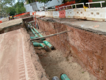
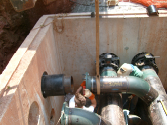
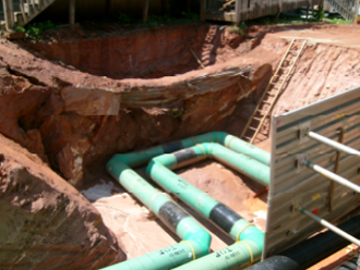
Over 8,000 linear feet of underground chilled water and high-temperature hot water piping were installed on the Spelman College campus. Eleven (11) cast-in-place concrete manholes were constructed for access to valved branch connections serving various buildings on campus. Existing below-ground utilities were located and rerouted, as required, to coordinate new utilities. The entire scope of work was completed over the summer months to minimize disruption of campus activities. Routing of pipe included through landscaped areas, beneath campus and City of Atlanta streets, beneath sidewalks, and under parking lots.
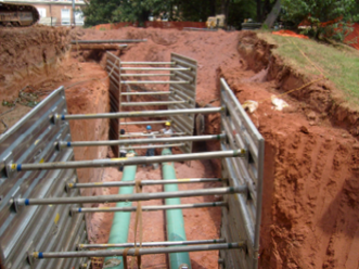
Average trench depth for new utilities was approximately 12 feet below grade. College stressed cleanliness of project; therefore, street sweepers were utilized everyday and water trucks kept dust minimized. Open excavations were protected for the protection of students on campus. Work was coordinated with scheduled campus activities.

Open Trench with High Temperature Hot Water

Piping Installed in Cast-In-Place Manhole

Open Trench with Trench Boxes (Note Men in 2nd Trench Box)

Open Trench with Hot Water and Chilled Water

Hot Water Expansion Loop